
Phasor diagrams are your one-stop-shop for understanding an electrical system at a glance. You’d think that all of the relay test-sets, phase-angle meters, and relays would use the same angle systems to communicate this important information to prevent confusion. Unfortunately, you’d be wrong.
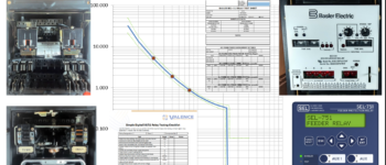
Imagine you’re testing an SEL relay using a Doble test-set and RTS software and you set up a simple three-phase, balanced, metering test (ABC). Each device would display the following angles during a typical meter test:
- A-Phase voltage = 0 degrees, B-Phase voltage = 120 degrees, C-Phase voltage = 240 degrees
- A-Phase voltage = 0 degrees, B-Phase voltage = -120 degrees, C-Phase voltage = 120 degrees
- A-Phase voltage = 0 degrees, B-Phase voltage = 240 degrees, C-Phase voltage = 120 degrees
[accordion][accordion_element title=”Can you confidently match the angle system to the device? (Write down your answers and click to compare {RTS = ?, SEL = ?, Doble = ?})”]RTS = 1, SEL = 2, Doble = 3[/accordion_element][/accordion]
If you don’t know the difference between devices, you won’t be able to:
- Perform a meter test properly (more on meter tests in the future)
- Create effective test-plans
- Troubleshoot test-plan problems
Can you believe that there is a fourth angle system out there we haven’t mentioned yet?
This course will introduce you to phasors and show you how to convert waveform drawings into phasor drawings so that you can understand what phasors are and how they are created. You will be able to understand what is happening inside your relay and test-set with these topics:
- What are Phasors?
- How to Draw Phasor Diagrams
- Drawing Phasors with Lagging Angles
- Drawing Phasors with Different Scales
In a perfect world, these four lessons would be all you needed to become a phasor drawing master. You would be a master at understanding and drawing phasor diagrams in Megger test-sets and GE SR relays but, unfortunately, it seems every manufacturer has a different system for the angles in phasor drawings. The remaining lessons in this course will help you understand all of the different angle systems used by test-sets from Doble, Omicron, and Manta Test Systems as well as the angle systems used by GE UR and SEL relays:
- Draw Phasors with Positive Angles
- Draw Phasors with Negative Angles
- Draw Phasors with Positive and Negative Angles
You get immediate access to the course if you pay with a credit card. All of our online courses include:
- High-quality video presentations introducing you to theory behind the topic to help you understand how it works
- Real-world examples that show you how to apply the theory
- Interactive exercises and quizzes that simulate the most realistic situations possible to help you learn by doing
- A comment section where you can ask your questions and get your answers from instructors or fellow students
You can watch a 10-minute video below that will give you an introduction to the topics covered in this course.
Still not sure if this course is right for you? Test your knowledge with this quick quiz:
Sign-up today if you can’t answer all of the questions correctly,
This course is eligible for 4 NETA Continuing Technical Development Credits (CTDs). NETA Certified Technicians (Level III and Level IV) are required to earn a minimum of 48 CTDs every three years to maintain their certification. For more information about the CTD program and requirements, please contact the NETA office at neta@netaworld.org or 888-300-6382.
Do you want to enroll more than one person in our online training courses? No problem! Click the “Enable Group Registration” checkbox at the bottom of any course, then choose how many people you want to register before you click “Add to Cart”. All bulk and coupon prices will still apply. You control who gets enrolled in the course via the “Group Registration” page. Enroll one at a time, or upload your entire team via a simple csv file. We’ll automatically create everything they need to start the course and send them an email with their username, password, and course links.

Reviews
There are no reviews yet.