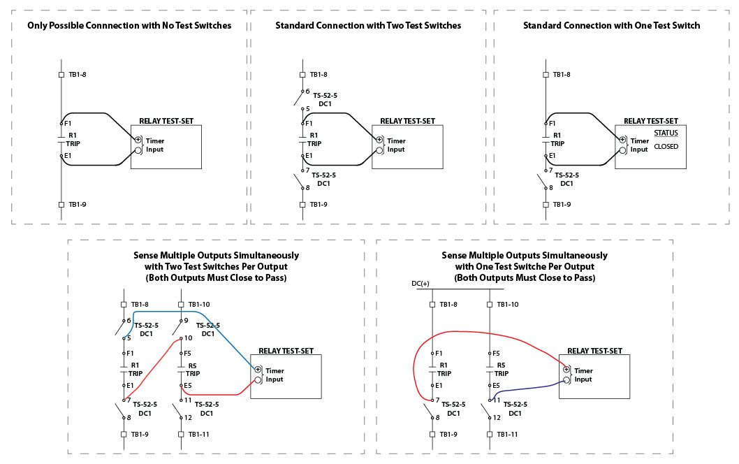
It is really easy for a design engineer to incorrectly program an output and unintentionally disable a relay, which could go undetected for years until it fails to trip during a fault.
These videos will show you how to create and/or modify your test plans to test multiple outputs at the same time to help make sure that this relay does EVERYTHING it is supposed to.
Valence Electrical Training Services is not endorsed, sponsored, or affiliated with any company, trademark, or owner of any trademarks presented in these videos. This material is intended for educational and informational purposes only and any use falls under the Fair Use Doctrine of Section 107 of the Copyright Act.
Click Here if You Use an Omicron Test-Set
Omicron Test Universe
Click Here if You Use a Manta Test-Set
Manta MTS-5000/5100
Click Here if You Use RTS Software to Perform Your Tests
Click Here if You Want to See More Videos About This Topic
Don’t forget that you can always physically connect multiple outputs in series and then connect the test-set sensing input in parallel with all the outputs if you want to test more than one input at a time.
- If you can isolate both sides of all of the relay outputs, you can connect an unlimited amount of contacts in series and test all of the outputs used for any particular element at once with one timing test.
- If you can only isolate one side of the relay outputs, then you can only test two outputs at once and will have to perform multiple timing tests for each element assigned to operate more than two outputs.

Click “Mark Complete” below after watching the video so you can keep track of your progress.

Would it be possible to get copies of the plans you used in these training videos for the Omicron? I would like to go through them and see how you made them which is a bit hard to do from watching the videos
It doesn’t look I saved after recording the video. I quickly mocked up the “51GT 2X” test in this file, which should be pretty close to the settings in the video.
Download the file
Hope it helps.
When the outputs are put in series, I believe OUT5 is connected incorrectly. I believe the polarity is backwards and the contact probably appears “closed”, so the test is really only testing OUT1.
I can see how you could make that determination when looking at the video.
I spent a lot of time making sure I got the right combination when testing the relay because it didn’t work correctly they way I though it should have. But I may have documented it incorrectly. Different relays might operate differently depending on their internal circuitry.
Always test your connections to make sure the connections are correct.
The test for this circuit would be to pulse OUT1 for 10 seconds and make sure you don’t see the contact close. Then pulse OUT3 before the 10 seconds expires and make sure you see the contact close.
Do the same test by reversing OUT1 and OUT3 in the previous test.