You may have seen this post from out TechTalk blog that discusses how to phase rotation with waveforms and phasor drawings. We added it here to make sure everyone gets a chance to read this important information.
Understanding phase rotation is vital when connecting two systems together because the results can be catastrophic if someone doesn’t understand how to interpret phase rotation drawings. You would think something as important as phase rotation would have consistent terms across the entire industry. Unfortunately, you’d be wrong.
Let’s start with a refresher on generator theory.
The video below shows a generator with “clockwise rotation” because the generator rotor is rotating clockwise inside the stator. I think this is a terrible definition because the rotor would appear to be rotating counter-clockwise if you walked it around and looked at the opposite side of the generator. It all depends on your perspective. Some people refer to the voltages created by this generator to be “clockwise” because if you start with A:
- the A-Phase Voltage reaches its peak first,
- followed by the B-Phase Voltage, and then
- followed by the C-Phase Voltage.
A counter-clockwise generator can be defined as a rotor that rotates counter-clockwise inside a stator as shown in the following video. Some people would refer to the voltages created by this generator to be “counter-clockwise” because if you start with A:
- the A-Phase Voltage reaches its peak first,
- followed by the C-Phase Voltage, and then
- followed by the B-Phase Voltage.
Both of these definitions are a terrible way to communicate phase rotation.
For example, which phase sequence is the voltage output of the generator in the following video?
The generator is rotating clockwise, but the voltages are counter-clockwise because the A-Phase Voltage reaches its peak first, followed by the C-Phase Voltage, and then followed by the B-Phase Voltage.
Which is the correct term for this system…clockwise or counter clockwise? Both apply, don’t they? That’s why this definition of phase rotation is confusing.
We don’t care which direction the generator turns in the power system. We want to know the order, or sequence, of voltages being produced by the generator and to make sure that the system has the same phase sequence before connecting the two. Therefore, you should banish clockwise and counter-clockwise from your terminology if you want to effectively communicate phase sequence information with someone else.
How to Determine Phase Rotation from Waveform Drawings
The correct terminology to use should reference the voltage designations, and always start with the same designation.
The A-B-C-A-B-C system in the next image is an A-B-C system if I choose A as a reference.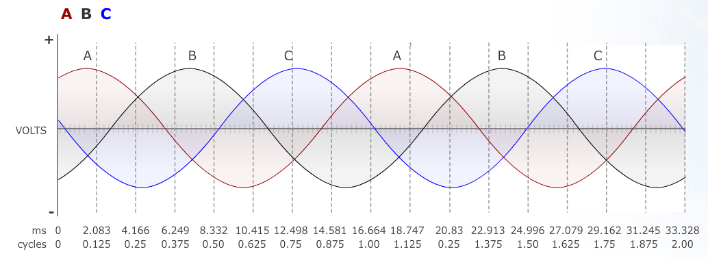
![]()
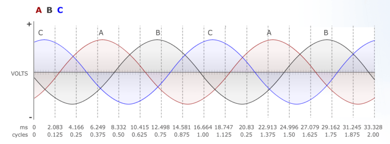
The image below shows a C-A-B-C-A-B system, which is also an A-B-C system if I use A as a reference. It could also be called a C-A-B system, or a B-C-A system, depending on the reference.
The image below shows an A-C-B system, or a C-B-A system, or a B-A-C system, depending on the reference.
What is the Best Way to Communicate Phase Sequence?
There are two rules you should use whenever communicating phase sequence, or phase rotation, information:
- Always use the voltage designations.
- Always start with the same designation.
If you always follow these two rules, there shouldn’t be any communication errors.
If you want more information about what we’ve discussed so far, you should check out our Online Course 1-1: The Three-Phase Electric Power System (4 NETA CTDs).
Determine Phase Rotation via Phasor Diagrams
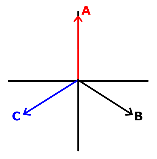
There is still a problem that I find in most of my classes…phasor rotation is NOT depicted by waveform drawings; they’re depicted in phasor diagrams. Many of my students can’t determine the correct rotation with typical phase rotation notations on a drawing like the following:
Let’s test your knowledge. Which phase rotation is the following drawing?
The phase rotation is A-B-C.
You can’t determine phase rotation with a phasor diagram unless you know the one universal rule in the relay testing world. ALL PHASORS ROTATE COUNTER-CLOCKWISE.
The video below shows you how the waveforms and phasors inter-relate.
Notice that the phasors rotate counter-clockwise and that the corresponding waveforms match the A-B-C rotation from the waveform drawings earlier?
There should always be an arrow indicating the direction that the phasors are rotating and it should always be pointed counter-clockwise.
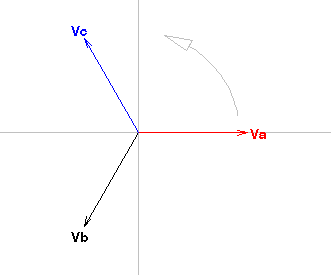
Which rotation is the phasor diagram below?
It is still A-B-C rotation. You can always tell rotation by imagining that the phasors are spinning like this video below.
If you want to be sure you understand phase rotation correctly, put your finger anywhere on the phasor diagram and imagine that the phasors are spinning counter-clockwise. Start paying attention when your reference phasor crosses your finger. Which phasor crosses your finger next? Which is the last phasor to cross your finger? This will help you determine the phase rotation as shown in the following video:
Let’s try another test!
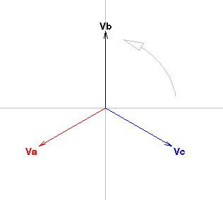
Which phase rotation is being generated in the following drawing?
It’s A-B-C again as per the following video:
Now that you know what to look for and how to determine the phase rotation,
Can You Determine the Phase Sequence Using Phasor Diagrams?
What is the phase rotation using 1 as a reference in the drawing below?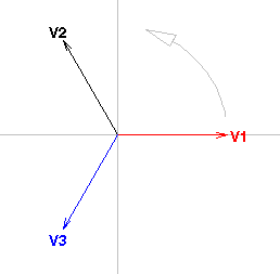
The phase rotation is 1-3-2 as per the following video:
You should be able to reliably determine the phase rotation of a system and to communicate that information effectively to someone else. The results can be catastrophic if you can’t, which is why this a vital skill all relay testers should know.
You can get more information about phasor diagrams with our Online Course 1-2: Phasor Drawings for Relay Testers (4 NETA CTDs).


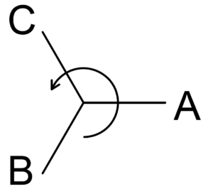
I use the mnemonics “cab” and “bac(k)” for ABC and ACB. It’s as silly as it is simple. Cabs (ABC) usually go forward, back (ACB) is going backwards.